Dubai, United Arab Emirates
https://elitelondontutors.com/
Alongside with my brother, I have founded Elite London Tutors, an online tutoring platform to reach expatriate students studying the British curriculum.
Having grown up in Dubai, we know firsthand the difference that good tutoring can make in obtaining a place at a top UK university. We are also aware of the dearth of good quality British tutors in expatriate regions, having struggled to find tutors during our GCSE and A-Level studies in Dubai.
With Elite London Tutors, we are sourcing the best local tutors from London, and making them available anywhere in the world via a virtual classroom.
My personal contributions have revolved around strategic planning, website development, and implementation of the virtual classroom.
For more details visit the website at https://elitelondontutors.com/
Tools used: Dassault Systemes SolidWorks, PTC Creo Parametric, Rapid Prototyping (3D Printing)
See website: https://www.chooseblocks.com
I was involved in the Blocks project early on in its industrial design phase as a part time engineer/consultant. I was brought on along with a colleague in the initial design phase of the watch body, as well as the electromechanical connector between modules.
The concept of the watch is to provide a fully functioning smartwatch as the main body of the watch, and instead of having a simple leather or plastic band, using 'smart' modules which link up and provide various functions. At launch, these functions are: GPS, extra battery, pulse sensor, humidity/temperature/altitude sensor, programmable button and a flashlight.
Designing a connector which meets multiple criteria constituted the bulk of my work. Key criteria included:
- Tensile strength
- Flexibility
- Maintaining good electrical contact throughout range
- User friendliness in connecting and disconnecting
- Watertightness
A number of unique designs were drafted, and prototyped with the aid of rapid prototyping. Testing was conducted and each design was evaluated against the original criteria to determine suitability.
The engagement ended with a number of prototype designs presented to the team.
All images on this page are property of Blocks Wearables Ltd.
Tools used: Massey 1000ton forging press, general milling and turning, furnace heat treatment, EDM wire cutting, optical microscopy, scanning electron microscopy, EDX spectroscopy.
Part of an Imperial Innovations project:
http://www.imperialinnovations.co.uk/license/available-technologies/lightweight-multi-material-gears/
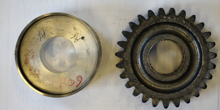
The objective of this process is to produce precision-forged bi-metal lightweight gears in a single step forging. Implementation of lightweight bi-metal gears to vehicle gears can result in weight savings of 30-50% over traditional steel gears.
The motivation for this is to be able to reduce the mass of rotating mechanical components, the benefit of which is substantially greater than reducing the mass of non-structural components. The vast majority of the rotational inertia of an automotive transmission comes from the gears themselves, and thus reducing this directly results in improved transient transmission performance, benefiting fuel consumption and acceleration speed.
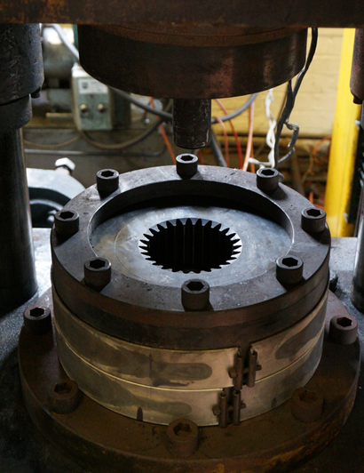
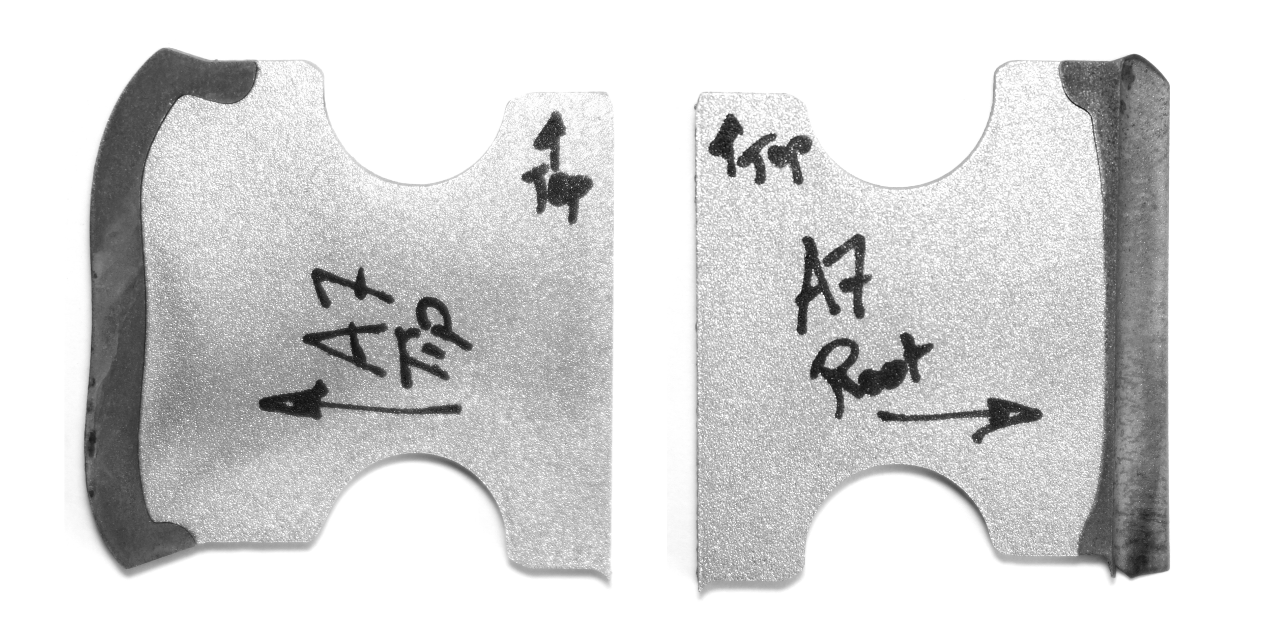
Trials have been conducted with combinations of materials including Al-6082/Carbon Steel, and Al-7075/EN24, as well as a range of different ring thicknesses. For the experimental trials, the steel and aluminium billets were heated to their respective forming temperatures independently in two different furnaces. The workpieces were then assembled concentrically in the die, and forged in a single step operation using a Massey 1000 ton forging press.
Gears were successfully forged in the trials, and were sectioned for analysis. Preliminary evidence of a weld at the interface between the two metals in certain regions of the gears has been discovered.
Details of the experimental setup as well as detailed results re presented in my PhD thesis.
Software/Equipment used: Dassault Systèmes SolidWorks, SIMULIA Abaqus 6.13, FORTRAN compiler, Imperial College HPC.
Part of an Imperial Innovations project:
http://www.imperialinnovations.co.uk/license/available-technologies/lightweight-multi-material-gears/
This project was the numerical parallel to the bi-metal lightweight gear forgings. Specifically, it is a numerical simulation of forging a steel ring and an aluminium core together to a unified bi-metal gear, reducing the mass of the part.
The objective was to generate a numerical representation of the forging process in order to determine a number of parameters, including:
(i) Overall press load-stroke characteristics
(ii) Interfacial properties, including pressure and shear
(iii) Bulk temperature to determine if any melting occurs
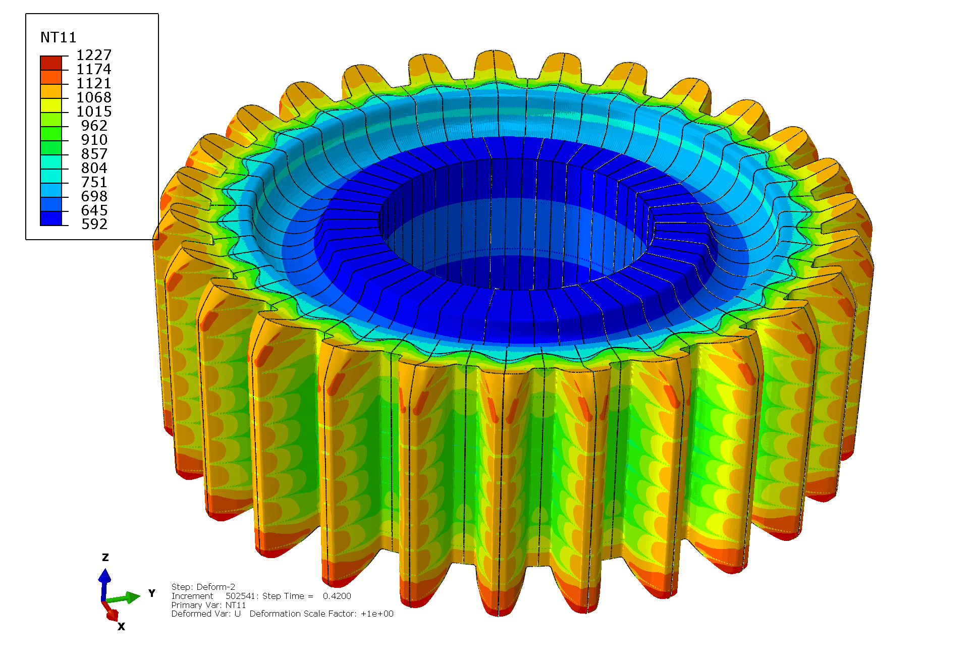
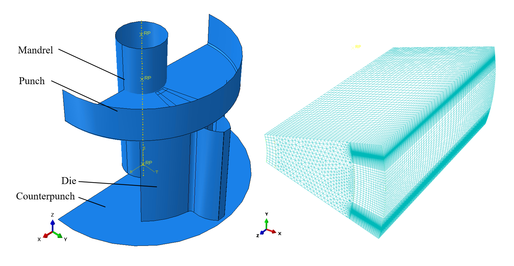
The numerical model was created using Simulia Abaqus 6.13. The model is of the dynamic explicit coupled temperature-displacement type. The modelling domain was chosen as half of a tooth, exploiting the inherent symmetry of the problem to reduce computational time.
Material properties are described using a material property subroutine (VUMAT) enabling accurate determination of the flow stress regardless of the temperature, strain, and strain rate at any element in the model.
Due to the large displacements and distortions occurring in the forging process, a very fine mesh is required, which is also adaptive to alleviate excess distortions. A total of 1.25 million elements were used in the workpieces, and an additional 120 thousand in the toolpieces (which we're also modelled to depict true-to-life thermal conduction).
A number of runs were conducted, adjusting the ring thickness and temperatures, to numerically analyse the actual forgings that we're conducted. Data from these simulations were used in further research into bonding at the interface.
Numerical data from the simulations are presented in my PhD thesis.
Software used: MathWorks MATLAB
Publication: A method of determining unified viscoplastic constitutive equations for hot forging simulations, 2016
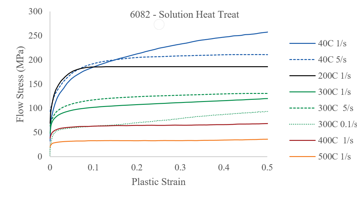
It is well documented that in the forging process, the material flow patterns, final shape, toolpiece pressure, and overall press load are heavily influenced by the flow stress of a material. In turn, this flow stress is dependent on both strain rate, and temperature. In order to accurately model the forging process, it is necessary for the Finite Element solver to be able to use accurate material properties (i.e. flow stresses) for every element in the workpiece, regardless of its’ temperature and strain rate. In order to achieve this, a set of unified visco-plastic constitutive equations can be used in a subroutine in the solver, which can describe the flow stress of the billet material at a range of temperatures and strain rates. These equations are an analytical representation of a physical material, whose material properties are determined by compressive testing. Through the use of the equations, the FE solver will be able to precisely determine the correct flow stress at a given temperature and strain-rate, regardless of the initial test conditions, and without having to use an inaccurate interpolation.
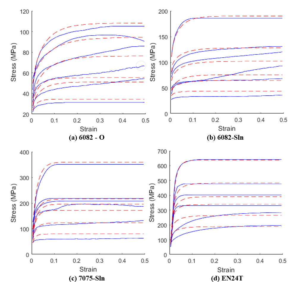
Experimental data was obtained my compressive testing of cylindrical material samples using a Gleeble 3800 thermomechanical testing machine. Steel (EN1A, EN24T), and Aluminium (6082-O, 6082-T4, 7075-T4) alloys were tested at a range of temperatures covering their forming temperatures, and at a range of strain rates (from 0.1 to 10), thus covering a range of forming conditions. Examples of experimental data are shown in the figures.
The constitutive equations used to describe the material properties are standard viscoplastic equations, utilising isotropic hardening and viscoplatic flow terms, as well as Arrhenius temperature dependency. These equations have the notable exception of a damage term, as the forging process is primarily compressive. There are a total of 14 constants to determine, which presents a particularly challenging computational problem.
This project attempts to address the problem by implementing a computational solver which minimises the error between the computational (derived from constants) and experimental material data, utilising readily available, robust optimisation engines.
A series of scripts were written in MATLAB which leverage the built-in Genetic Algorithm solver to quickly determine several “good enough” guesses of sets of constants, then runs the more efficient Simulated Annealing solver to converge upon the best solution. This is a heuristic search method to find a ‘good-enough’ set of constants that minimise error. Given the incredibly large search space, and lack of initial guesses by the user, it is a more realistic approach than attempting to find a single, absolute best set of constants with the lowest possible error.
Resulting fits are shown in the images. These fits were obtained within 24 hours on a Core i7-4770, with no initial guesses by the user. The constants can subsequently be used in FE analyses for more accurate material properties.
Software/Equipment used: Simulia Abaqus 6.12, Instron 2.5MN servohydraulic testing machine, general milling and turning
Publication: An experimental and numerical investigation into forming force reduction in precision gear forging, 2014.
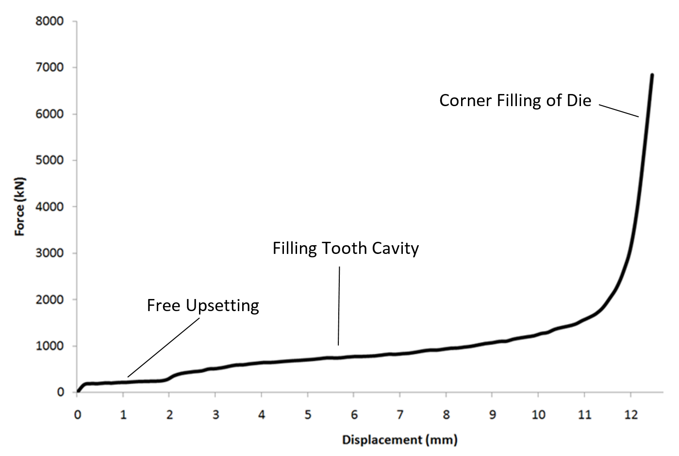
A significant factor in the cost of industrial machinery for precision forging is the maximum load required to fully forge the final shape of components. Typically in a precision forging process, the required load increases greatly towards the end of the stroke. This study focuses on reducing the final sharp increase in load encountered in a typical closed die forging setup.
In an example case of precision gear forging, it is commonly known in the literature that the final stages of filling the tooth tips with material constitutes up to 2/3 of the total press load required to forge a precision gear. This means that a significantly larger press is required to fill the tips compared to the bulk forming of the gear, thus substantially increasing the initial investment required for precision forgings compared to traditional forgings. An example of a load-stroke curve is shown in the images.
A number of tooling modifications were investigated numerically using Simulia Abaqus to produce an explicit finite-element model of the forging operation. For simplicity of the simulation and material properties, an isothermal, rate-independent simulation was developed, simulating a single tooth to minimise computational time.
This model was used to investigate a large number of tooling and workpiece designs intended to reduce the forming load. Those investigated include methods described in the literature, as well as new methods introduced in this study.
Simulations showed that the most simple and effective method involves leaving a gap at the tooth tip (the final point of filling). This method, called the “Peripheral Relief” method, allows workpiece material to flow out of the enclosed die cavity at the end of the forging operation, thus eliminating the sharp increase in forming load at the end of the forging process. An image of the FE simulation of the project is shown.
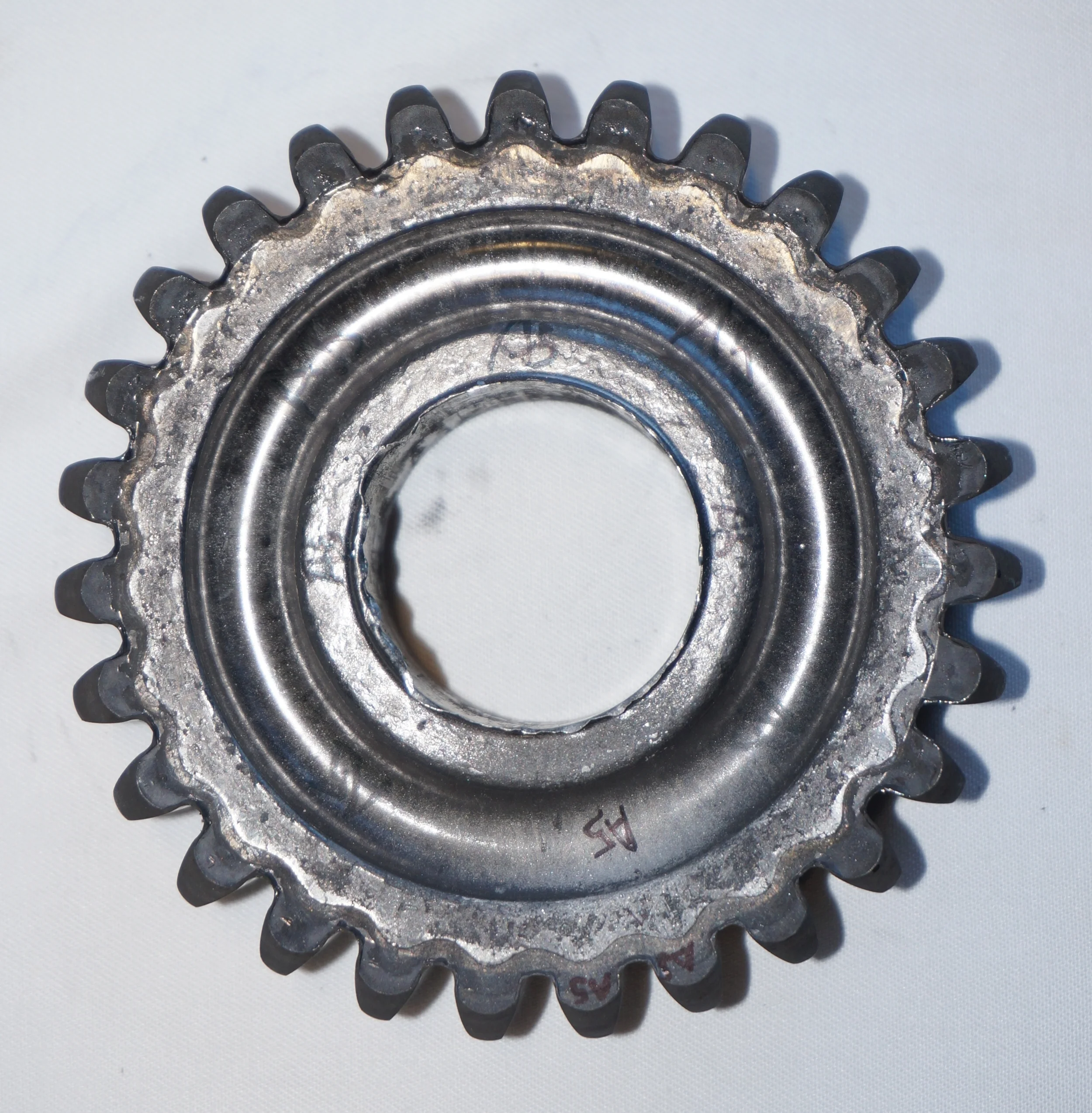
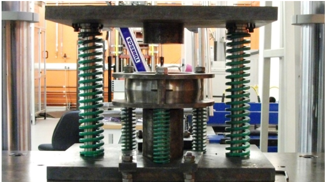
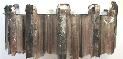
To verify the simulation, experimental trials were conducted utilising a 2.5 MN Instron dynamic testing machine. The test rig used is shown in the images, along with a resulting gear. Commercially pure aluminium was used as a model material as it is sufficiently soft for room temperature work, as well as strain rate independent, thus removing several variables from consideration.
In order to effectively utilise this method, it is necessary to carefully control the stroke of the press, to prevent excess material from being extruded from the relief port. Appropriate stroke can be determined from numerical simulations.
Force reductions of up to ~60% are possible with significant material loss at large relief port sizes, however for more practical applications, load reductions of approx. 10-30% are possible with negligible material loss.
Software used: Dassault Systèmes SolidWorks, MathWorks MATLAB, Simulia Abaqus 6.11
Equipment used: General milling, turning and other workshop skills, Rolling road dynamometer, vibrations analysis equipment (accelerometer, signal conditioner, impulse hammer, signal analyser)
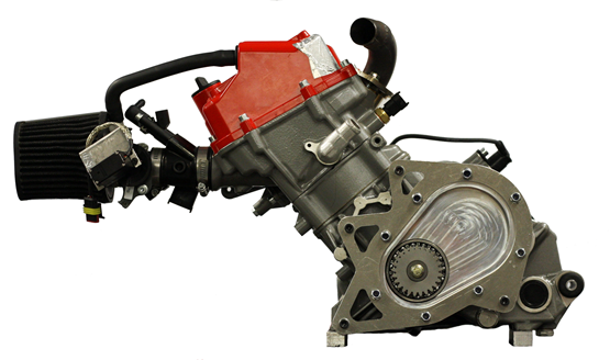
This project was a group effort of 5 Imperial College 3rd year students including myself to design, manufacture and test the Range Extender Gearbox (REX), a transmission system linking a 250 cc single-cylinder combustion engine to an electrical generator. The motivation of this project was to develop a hybrid propulsion system for the upcoming Formula Student racing vehicle.
Two main tasks were accomplished: the design and manufacture a temporary test rig and transmission for bench testing of a chain drive between engine and generator, and the design of the final transmission.
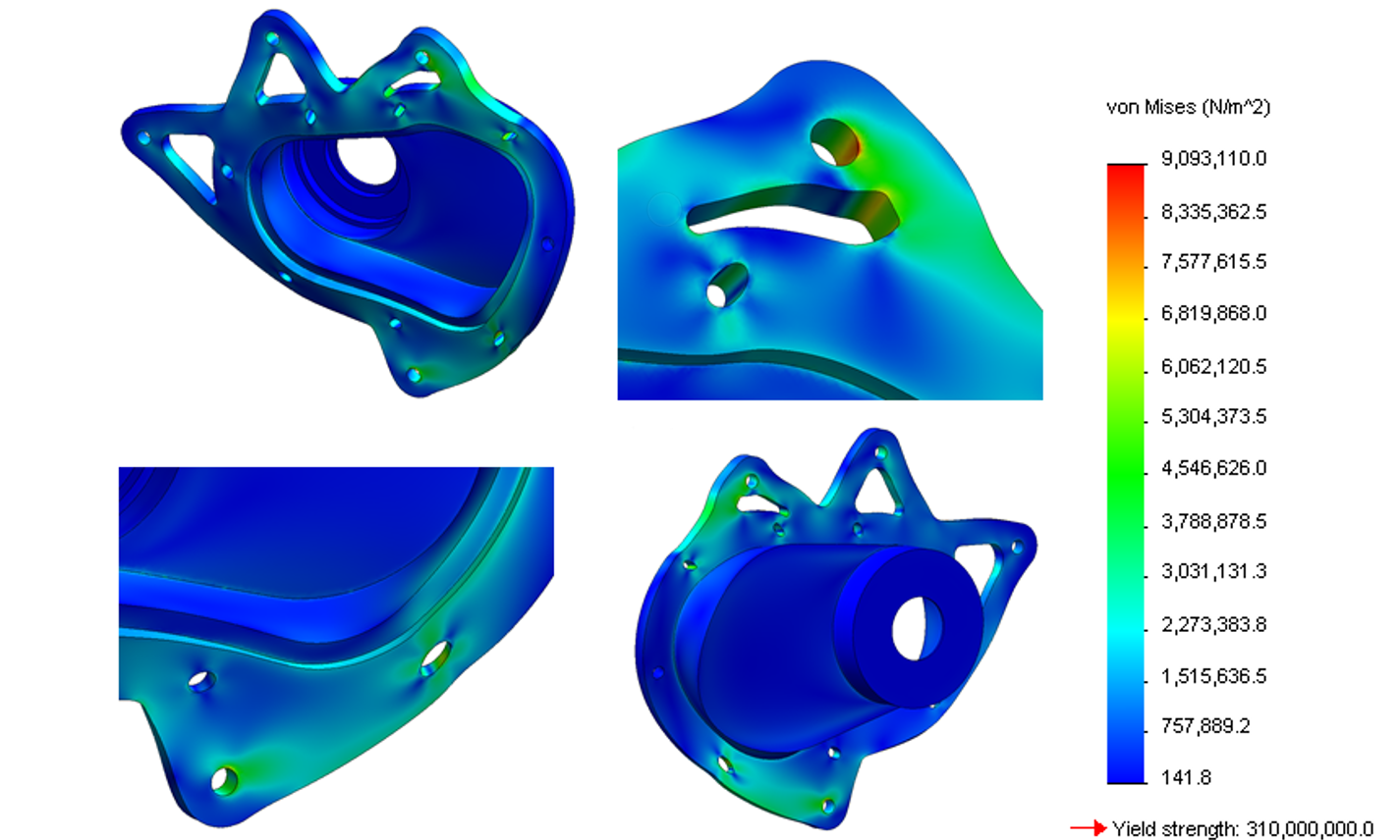
During the different stages of the project, a number of design concepts were developed through the Quality Function Deployment (QFD) technique. Heat and stress analyses were performed to validate design decisions and optimise the configuration of the gearbox and engine. The final design was 25% below the target weight of 4 kg.
Heat transfer analysis of the gearbox showed that the maximum temperature that the gearbox oil would achieve during a race is 110oC. An SAE80W90 lubricant was found to be an appropriate specification and that it is unnecessary to implement fins or a cooling fan. In addition, Finite Element Analysis carried out on the gearbox yielded a maximum stress of 19.05 MPa, suggesting that the gearbox casing is not in danger of yielding or fatigue failure.
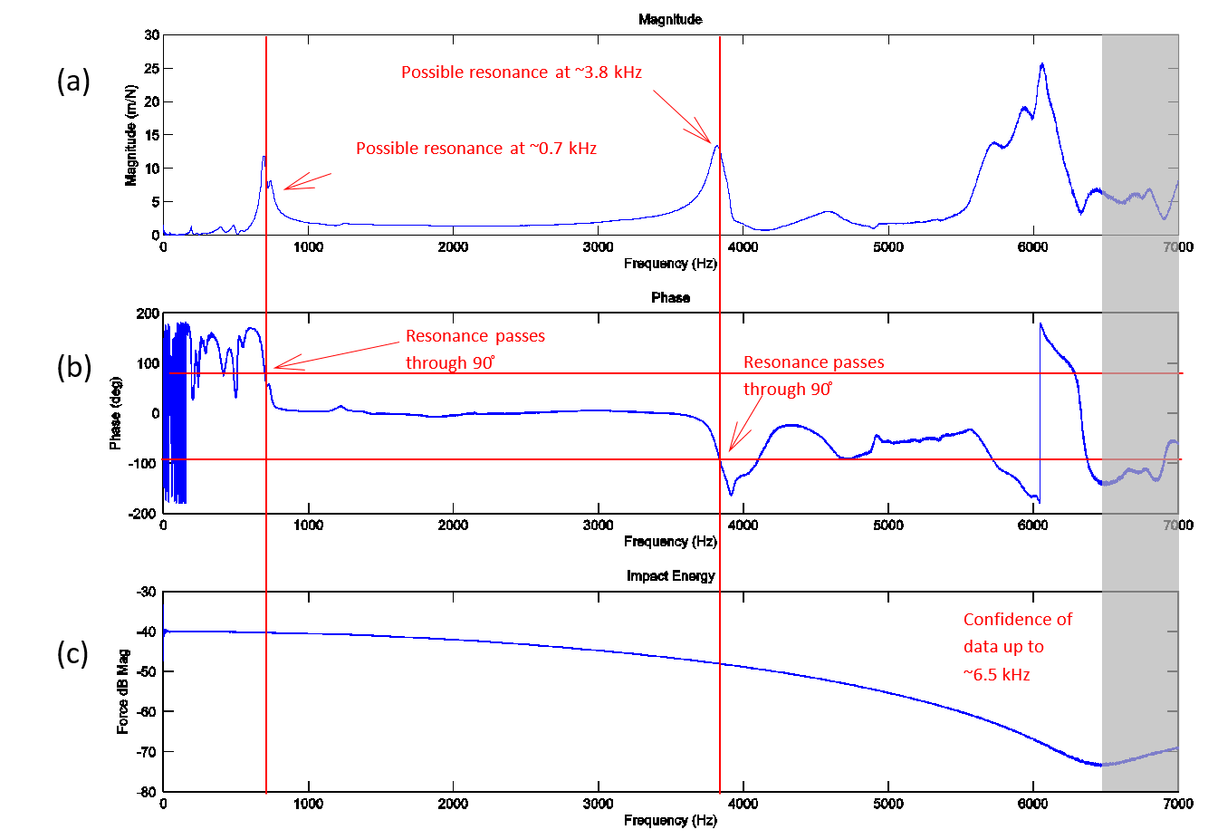
The gearbox was CNC machined in-house from 6082-T651 aluminium. The gears used were customised and required outsourced manufacturing. Finally, an impact hammer vibration test determined three main resonant frequencies of 3800 Hz, 1900 Hz, and 700 Hz and a damping ratio of 0.06. It was determined that the structure would not be subjected to resonance conditions during operation.
All objectives were completed in accordance with project deadlines. A critique found at the end of the report comments on the design and manufacture of components, and provides information on the gearbox for future use.